
Everything about spark plugs and ignition systems
Practical answers for stationary gas engines and CHP units. And the team that helps you choose.
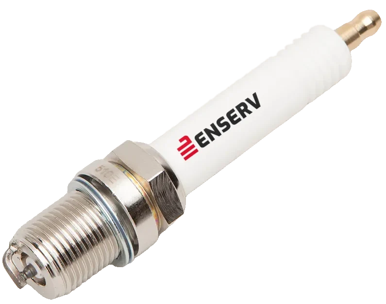
Everything has to fit together
Good ignition does not come from a single part, but from a matched chain. Each link determines what the next one has to deliver.
Engine
Manufacturer, type and combustion chamber determine heat range and design.
Gas and mixture
Gas type and mixture ratio determine the ignition demand.
Ignition system
Voltage and energy must match the electrode gap.
Spark plug
Heat range, thread and gap must match the engine.
Exhaust and sensors
Sensors and catalytic converter show whether everything works together.
How it works, at a glance
Five short journeys show step by step how the components work.
Advice that makes the difference
The right spark plug depends on the engine, the ignition system, the gas and the operation. That is why we do not decide from a catalogue, but together with you: expert, direct and tailored to your plant.
Since 1980
Experience with stationary gas engines and CHP units
DIN EN ISO 9001:2015
certified quality management
Directly by phone
Please have ready
- Engine manufacturer and type
- Year of manufacture or serial number
- Designation of the current spark plug
- Operating hours and last replacement
- Gas type and existing ignition system
- Anomalies such as misfires or knocking
Frequently asked questions
Spark plugs
The spark plug carries the high-voltage pulse of the ignition coil through the centre electrode to the tip. A spark jumps between the centre and ground electrode and ignites the compressed gas-air mixture in the combustion chamber. Every step is shown in the journey how a spark plug works.
Terminal, ceramic insulator, centre electrode, metal shell with thread and ground electrode. The insulator separates the high voltage from the shell. The shell grounds the plug and conducts heat into the cylinder head.
The electrode gap is the space the spark jumps across. If it is too large, the spark needs more voltage and misfires may occur. If it is too small, the spark becomes weak and the flame kernel develops less well. The engine manufacturer specifies the correct value, and it is closely tied to the ignition system.
The heat range describes how much heat a plug dissipates. A plug that is too hot can cause pre-ignition, one that is too cold fouls because it does not burn itself clean. The right heat range depends on engine, load and gas type.
Nickel alloys and precious metals such as platinum and iridium are common. Precious metals wear more slowly and allow thin electrodes. Whether that pays off depends on the engine and the manufacturer’s specifications.
That depends on the engine manufacturer’s specifications, usually in operating hours, and on actual wear. Regular visual inspections show early how far the electrodes have burnt down.
Typical signs are rough running, misfires, rising ignition voltage demand, worse exhaust values and burnt or fouled electrodes. With gas engines it pays to document these values over time.
Matching
Spark plug, ignition system, engine and gas quality form a chain. The ignition system must supply enough energy and voltage for the electrode gap. The plug must suit the temperature in the combustion chamber, and the mixture must remain ignitable. If one link is not matched, smooth running, service life and exhaust values suffer.
Possible consequences are misfires, pre-ignition, knocking and rapid wear. In the worst case, engine damage can occur. Worse exhaust values and higher consumption are also possible.
The ignition system generates the high voltage, the plug turns it into a spark. Electrode gap, ignition voltage and ignition energy must match. That is shown in the journey from signal to spark.
Depending on the gas, for example natural gas or biogas, and the mixture composition, ignitability and burning speed change. A lean mixture generally needs more ignition energy. Gas quality and ignition should therefore be considered together. How the gas reaches the engine is shown in the journey the path of the gas.
Knock sensors and NOx probes give the control unit the values used to regulate ignition timing and mixture. Faulty sensors lead to wrong control actions. More in the journey measuring and controlling.
Filters protect the engine, gas train and oil circuit from contamination, the catalytic converter cleans the exhaust. Both affect service life and exhaust values. More in the journey clean air, clean exhaust.
Products
ENSERV offers spark plugs (including special spark plugs), ignition systems as well as systems for engine control and regulation, sensors, gas trains with gas valves, throttle valves, regulators and actuators, catalytic converters, filters for air, oil and gas, spare parts and accessories.
ENSERV specialises in stationary gas engines and CHP components. On the website, products can be selected by brand and engine. Tell us your engine and together we will find the right solution.
It is in preparation. Until then, the team will advise you personally on choosing the right spark plug.
The spare parts are new and match in quality the components the engine manufacturer installs at the factory.
Accessories include timing lights, tools, connectors and adapters.
Advice
You describe your engine and plant, we match spark plug, ignition system and other components together and answer your questions on installation and operation. You can reach us by phone at +49 (0)5141/7548-0 or by e-mail at info@enserv.de.
Helpful are: engine manufacturer and type, year of manufacture or serial number, the designation of the current spark plug, operating hours and last replacement, the gas type, the existing ignition system and any anomalies such as misfires or knocking.
Because the parts work together. A spark plug that fits by catalogue number can still be wrong if the ignition system, gas type or application differ. A short conversation saves wrong purchases and downtime.
ENSERV EIS GmbH in Celle is your specialist for stationary gas engines and CHP components. The company has been active since 1980 and is certified to DIN EN ISO 9001:2015.
Phone +49 (0)5141/7548-0, e-mail info@enserv.de. Address: ENSERV EIS GmbH, Wernerusstraße 33, 29227 Celle, Germany.

The journey of the spark
Assemble a spark plug part by part and follow the spark to the explosion in the cylinder.
Start journeyScroll through the journey or use the “Next” button.
The insulator is the base
Alumina ceramic
It insulates the voltage from the shell and conducts heat away. The ribs lengthen the path along the surface so that current does not flash over on the outside to the metal.
The centre electrode is inserted
Tip only 0.4–0.6 mm thin
A copper core in a nickel alloy carries the current through the insulator to the tip, often made of iridium or platinum. The thinner the tip, the higher the field strength and the less voltage the spark needs.
The terminal closes the top
The only contact to the outside
This is where the plug connector or the pencil coil attaches. Everything else hangs on this single point: the current must reach the tip via terminal and electrode.
The shell grounds and cools
Thread = ground + heat path
The steel shell carries the thread and the bent ground electrode. It returns the current to ground and conducts the heat of the tip into the cylinder head. The heat range of the plug depends on it.
The plug sits in the cylinder
The mixture is compressed
Screwed into the cylinder head, the tip protrudes into the combustion chamber. In the compression stroke the piston squeezes the air-fuel mixture to a fraction of its volume. Pressure and temperature rise. Now is the right moment.
The pulse sets off
20,000–40,000 volts
Shortly before top dead centre, the ignition coil steps up the 12 volts of the on-board voltage. The pulse runs via the terminal and the centre electrode into the tip. The voltage builds up within microseconds.
The spark jumps
approx. 0.7–1.1 mm gap
The voltage rises until the gas in the gap ionises and becomes conductive. Then it collapses and a spark channel forms. It burns for only a few milliseconds, but reaches several thousand degrees.
A flame kernel forms
From spark to fire
The mixture at the spark ignites and forms a small flame kernel. It grows into a flame front that spreads spherically from the ignition point through the combustion chamber.
The explosion in the cylinder
over 2,000 °C, 30–60 bar
The flame front captures the entire mixture, temperature and pressure shoot up. Strictly speaking this is not a detonation but a fast, controlled combustion. If the mixture instead ignites uncontrolled on its own, this is called knocking.
The piston is pushed down
Heat becomes motion
The gas pressure pushes the piston down. Via connecting rod and crankshaft this becomes rotary motion. This is the power stroke. The spark has done its job.
And then again from the start
At 6,000 revolutions per minute, a four-stroke engine fires each cylinder every second revolution, so 50 times per second. The same journey takes place every time. In stationary gas engines and CHP units it matters that the plug does this reliably over thousands of operating hours.
Get in touch nowAll values are typical orders of magnitude and vary by engine and plug type. The graphic is schematic.From signal to spark
Follow the ignition pulse through an ignition system: from the sensor via control unit, ignition module and ignition coil to the plug.
Start journeyScroll through the journey or use the “Next” button.
The sensor reports the position
Keeping an eye on the crankshaft
An inductive or Hall sensor scans a toothed wheel on the crankshaft or camshaft. From the teeth and the gap the system detects speed and piston position.
The control unit decides the moment
Ignition timing in degrees of crank angle
It calculates from speed, load and knock signals when to ignite, in modern systems for each cylinder individually. Then it sends a switching signal to the ignition module.
The ignition module switches
Current on, store energy
The output stage in the ignition module switches on the coil's primary current. During this dwell time a magnetic field builds up and stores the ignition energy.
The coil steps up the voltage
20,000–40,000 volts
When the current is switched off, the magnetic field collapses. In the secondary winding with many more turns, the high voltage is generated.
The high voltage finds its way
Shielded and suppressed
Ignition cables or plug connectors carry the pulse to the spark plug. Shielding and suppression prevent the pulse from disturbing the engine electronics.
The spark ignites
The end of the chain
At the spark plug the spark jumps across the electrode gap. If the ignition system does not suit the engine, it ignites too early or too late. That is why it must be matched exactly to the respective engine.
An ignition system for every engine
Sensor, control unit, module and coil must fit together. For stationary gas engines and CHP units that means: ignition systems matched to the respective engine.
View ignition systemsGet in touch nowAll values are typical orders of magnitude and vary by engine and design. The graphic is schematic.The path of the gas
Follow the gas through a gas train: from the supply line via valve, filter and regulator to the engine.
Start journeyScroll through the journey or use the “Next” button.
Shut-off valves secure the line
Closed as soon as something happens
Solenoid valves open only while energised and shut off the gas in case of a fault or power failure. Often two valves are installed in series so that one alone seals reliably.
The filter holds back dirt
Clean valves, clean combustion
Gas can carry particles and moisture. The gas filter catches them before they wear out valves, regulators and actuators.
The regulator keeps the pressure constant
Same inlet pressure, always
A diaphragm works against a spring. This regulates the fluctuating mains pressure to the value the engine needs.
The actuator meters
Quantity according to load
An actuator moves the throttle valve or metering valve. The engine control unit uses it to determine how much gas flows into the mixture.
In the cylinder, gas meets air
Mixture instead of gas
The metered gas is mixed into the intake air and enters the combustion chamber. There the spark plug ignites the mixture.
Every stage counts
Valve, filter, regulator and actuator work as a chain. If one link fails, the whole engine suffers. For gas engines and CHP units it is therefore worth keeping an eye on the gas train.
View gas trainsGet in touch nowAll values are typical orders of magnitude and vary by engine and design. The graphic is schematic.Measuring and controlling
Two sensors keep a gas engine clean and healthy: the knock sensor on the block and the NOx probe in the exhaust.
Start journeyScroll through the journey or use the “Next” button.
The knock sensor listens in
Structure-borne noise of the engine
Knocking combustion creates vibrations in the range of a few kilohertz. A piezo crystal in the sensor converts them into an electrical voltage.
The signal is evaluated
Knocking or normal noise?
The control unit filters the signal and evaluates it cylinder-selectively in a time window around top dead centre. That is how it detects real knocking.
The control intervenes
Ignition later, engine protected
When knocking occurs, the control unit retards the ignition timing or adjusts mixture and load. This protects pistons, cylinder head and spark plugs from damage.
The NOx probe measures in the exhaust
Nitrogen oxides in ppm
The sensor sits in the exhaust line. Its ceramic element detects the nitrogen oxide concentration in the passing exhaust and reports it as a signal.
Measure, compare, readjust
Meeting limit values
The measured values feed into mixture control and exhaust aftertreatment. This keeps the engine within the permissible range and running efficiently.
No measurements, no control
A faulty sensor delivers wrong values, and the control then regulates in the wrong direction. That is why suitable replacement sensors for knock detection and NOx monitoring are important.
View sensorsGet in touch nowAll values are typical orders of magnitude and vary by engine and design. The graphic is schematic.Clean air, clean exhaust
A gas engine needs filters before it burns, and a catalytic converter after it has burnt.
Start journeyScroll through the journey or use the “Next” button.
The air filter protects the engine
Dust stays out
Particles in the intake air act like abrasive on cylinder walls and piston rings. The pleated filter medium offers a large surface at low flow resistance.
The gas filter catches contaminants
Protection for valves and regulators
Gas can carry particles and moisture. The filter sits upstream of valves, regulator and mixer and keeps them clean.
The oil filter keeps the circuit clean
Wear particles out, oil in
The oil pump moves the oil through the filter. Wear particles and combustion residues remain trapped, clean oil lubricates the bearings.
The mixture burns in the engine
Air and gas become exhaust
In gas engines and CHP units the exhaust contains, among other things, carbon monoxide and formaldehyde. Neither should reach the environment.
The catalytic converter cleans
Honeycomb body with precious metal
The exhaust flows through a honeycomb body with a catalytic coating. On this surface carbon monoxide and formaldehyde convert to carbon dioxide and water.
Maintenance keeps it running
Replace before it gets expensive
Clogged filters increase the pressure drop and let dirt through. A poisoned or clogged catalytic converter loses effect. Regular replacement and inspection secure performance and exhaust values.
Clean in, clean out
Air, gas and oil filters protect the engine, the catalytic converter protects the environment. For gas engines and CHP units, both sides belong together.
View filtersView catalytic convertersGet in touch nowAll values are typical orders of magnitude and vary by engine and design. The graphic is schematic.